
CANdb support for programmable terminals
![]()
![]() (caution: only available for certain terminals, not for CANopen)
(caution: only available for certain terminals, not for CANopen)
Overview
- Introduction
- Basic operation
- Import CANdb files and similar databases
- Select signals from the database
- Transfer signal definitions into display variables
- Develop and test the UPT display application
- CAN database import options and other features
- Assigning variables / CANdb signals to the lines of a display page
- CANdb file history (useable for 're-loading' modified databases)
- Options for importing CAN database files (*.dbc) / Overwriting already imported data
- Options for the conversion of CAN signals into display variables
- Signal timeout monitoring
- Special components of display variables for CAN / modifying signal definitions at runtime
- Signal Value Tables
- Details about the 'CAN Message Layout' display window
- Transmitting CAN signals (assembled into messages using info from imported databases)
- Appendix
- Strategy to allocate CAN message objects (for old devices with 'FULL-CAN' controller)
- Legal terms, disclaimer
- Last modifications (revision history of this document)
See also:
- Importing CAN/CAN FD signal- and PDU definitions from AUTOSAR XML
- Manual for the programming tool (not CANdb-specific)
- Frequently Asked Questions
- The Feature Matrix - tells you which of MKT's programmable terminals support CANdb at the moment
The programming tool can only read a small subset of the objects which may be contained in a CANdb network file.
Supported by the CANdb display terminal (as of 2014-01) :
- Data signals with 1..32 bit, travelling over the CAN-Bus as SIGNED or UNSIGNED INTEGER VALUES
- Data signals with 32 or 64 bit, travelling over the CAN-Bus as FLOATING POINT values
- Multiplexers and multiplexed signals (once called "mode signals" and "mode-dependent signals" or "multiplexors")
- Motorola or Intel byte order
- Conversion factors and offsets from the raw "signal" value into a floating point number for the display
Not supported by the CANdb display terminal:
- Integer values with more than 32 bits per signal
- Floating point values which are not 32 or 64 bit
- Enumeration values with text strings
- "Attributes" (with a few exceptions)
The "CANdb display terminal" alias "MKT-View" is a special variant of MKT's UPT (User Programmable Terminal), which only uses 'Variables' internally. Some of these variables may be connected to 'Signals', while other variables may be connected to the outside world via CANopen-SDO and PDO. Other variables may be unconnected, to use them only 'locally' for temporary storage inside the terminal application.
Basic operation
These basic steps are required to use CANdb-Signals in a terminal application:
Import signal definitions from a CANdb
network file |
Check and select CANdb Signal
definitions |
Transfer signal definitions to variables |
Develop and test the display application |
Download the application into a "real" terminal |
To use signal definitions from a CANdb file, switch to the tool's CAN tab.
With the buttons Load DBC #1 and Load DBC #2 buttons, import some signal definitions.
The signal definitions will be shown in a definition table.
To use some signals in the terminal later, you supply a unique variable
name for every used signal.
In contrast to a CANdb signal name, a variable name must always begin with
an uppercase letter to be recognized later by the display interpreter, and
the length of a display variable name may be restricted !
You can either type a variable name in the left column of the table, of double-click into a line of the table to generate a variable name automatically from the CANdb signal name.
After defining variable names for all signals you want to use, you can transfer them to the "Variables" sheet (which was there a long time before the implementation of the CANdb support).
Click the button Ready, transfer to Variables for this purpose.
You are now ready to use the variables in your display application just like any other (connected to SDO, PDO, or not connected at all).
Import signal definitions from a database (e.g. "CANdb network file")
To use signal definitions from a CANdb file, switch to the tool's CAN tab.
If there are old signal definitions in the table which you don't need any longer, click on Menu ... Erase the whole table before importing DBC files, or at least delete all unconnected signals (see notes below). Erasing 'the whole table' will also delete all connections between CAN signals and display variables, as explained later.
Then use the buttons Load DBC #1 and Load DBC #2
to import some signal definitions.
Load DBC #1 imports CANdb files for the first CAN Bus.
Load DBC #2 imports CANdb files for the second CAN Bus
(if the target device has two CAN interfaces).
- Note:
-
The button labelled "Other DBC" can be used to import dbc-files for
other buses (not limited to CAN, but also Ethernet / FlexRay). For Ethernet
/ UDP and the planned FlexRay/Ethernet-Converter, the CAN-specific 8 byte
limitation does not apply. This function was not completely implemented at
the time of this writing (2011-06-16). The ports "CAN3" and "CAN4" are reserved
for CAN-via-UDP.
Besides importing *.dbc files, some variants of the programming tool also support imports from AUTOSAR XML (*.arxml). Due to the incredible complexity and the huge number of different variants/versions of AUTOSAR, we cannot guarantee that all flavours of *.arxml can successfully be imported by the programming tool. Details about importing CAN signal definitions from AUTOSAR XML (and how to select signals for the display) will be available in a separate document.
For one of our customers, the NODE- and MESSAGE names must be ignored when overwriting old signal definitions. By default, an old entry in the table will only be replaced, when there is a complete match for NODE+MESSAGE+SIGNAL name. Click on the Menu button, then select CANdb File Import Options to change this. More info about the CANdb import options can be found in another chapter.
The signal definitions will be shown in a definition table on the "CANdb" tab :
Imported CAN database with the old 'Three-List-Selector'
Note that the column VarName is empty after importing signal definitions from a CANdb file.
On the left side of the CANdb Import Page, you can select a single node (blue list), a message from that node (green list), and a signal from that message (white list). The selected message will be highlighted in the table. Other signal definition lines from the same message are marked with a light blue frame, other messages from the same node are marked with a light green frame.
You can select a single signal by clicking into one line (row) of the definition table, or in the listbox Signals of message.
- Note:
- If you have hundreds of signals in different nodes and messages, first select the node, then the message, and finally the signal. This is much faster than scrolling through hundreds of lines in the definition table.
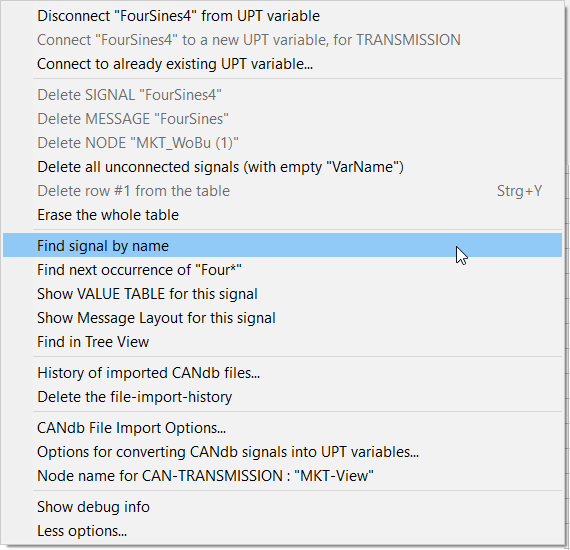
Right-clicking into any of the lists or the CANdb definition table opens a popup menu which shows all options for the currently selected node, message, or signal.
The columns in the definition table are:
-
VarName
Will be explained in another chapter. -
Bus Nr
1 for the first CAN interface, 2 for the second CAN interface (if supported by target hardware) - Signal Name
-
Type
For signals from CANdb files, only "Signed" and "Unsigned" (a big difference to CANopen !) -
Unit, Factor, Offset, Min Value, Max Value
Properties of a signal, read from the CANdb file. -
Mapping
Will be required later to extract a signal from a message. The first parameter is the bit position of the signal's least significant bit within a CAN telegram; no matter if INTEL or MOTOROLA, the bits in the first byte are numbered from 7..0. (beware: some CANdb editors use a different numbering system).
See also: Notes about the counting of bits within a CAN- or LIN-frame at the end of this chapter. -
Attributes
Not used yet. We don't support attributes.
( Sometimes the programming tool even crashes on exit, if an imported CANdb file contained attribute definitions. We are still tracing this bug ) -
Message Definition
Will be required later in the terminal to program the CAN controller for receiving the desired CAN message. The first part of the definition is the CAN identifier, the second part is a flag if 11 or 29 bit identifier shall be used (standard or extended frames) -
Multiplexer (alias "Multiplexor" or "Mode Signals" and "Mode-dependent signals")
Multiplexers are sometimes used if more signals shall be distributed via CAN than the 8-byte data field would allow, without sacrificing additional CAN message identifiers.
Depending on the multiplexor, the rest of the CAN message data field is decoded in a different way ("as if transmitted with a different ID"). In contrast to AUTOSAR-PDUs, a simple CAN-signal-multiplexer is always part of the CAN message that also contains the multiplexed signal (or even multiple multiplexed signals, using the same multiplexer signal). Thus the UPT programming tool uses the following simple syntax for a multiplexer (note the absence of a CAN message ID in the "multiplexer):
Multiplexer Value, Position of the Least Significant Bit, Length of the multiplexer in bits, 'I'(ntel)/'M'(otorola) byte order .
The same syntax is also used in the CAN-Simulator which, since 02/2021, can also send (transmit) CAN messages with multiplexers.
-
Comment
May contain a few letters from the 'comment' field of a signal definition.
- Note 1:
- Except for the VarName column, it makes no sense to edit the fields in this table ! Use an external CAN database editor like the tools from Vector or Kvaser to modify the signal definitions in your *.dbc file, and then re-import the definitions into the terminal programming tool.
- Note 2:
- In previous versions of the programming tool, it was necessary to erase the whole table before importing CANdb files (otherwise you ended up in a chaos of duplicate definition lines). Now, every signal definition read from the CANdb file is compared with the old contents of the table. If a definition line already exists, it's your decision what to do: You can either overwrite the old definition (with the column VarName being preserved) or append the new line to the table (which causes duplicate definition lines, you must remove the dupe's manually afterwards).
- Note 3:
- A history of the last 8 imported CANdb files is saved as part of the terminal project. This makes project management easier, because the CANdb file import history also has the timestamp of the loaded files.
The layout of a CAN message can also be displayed in graphic form. This helps to resolve problems with the bit numbering scheme, which can be extremely confusing if you use CANdb editors from different manufacturers (for example, some reverse the bit numbering in a CAN frame depending on a message type. We don't... we always use the same bit numbering scheme within a CAN- or LIN-frame, also when accessing the data field in the script language ). Here is an example for a graphic display of a CAN message with various CAN signals (click on the Graphics button on the CANdb tab to open it) :
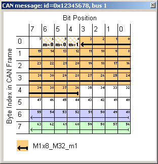
Screenshot of the graphic CAN message display.
Hatched bits show a signal's multiplexor.
Signals are marked by arrows; they point from LSB (start) to MSB
(arrowhead).
Details about the 'CAN Message Layout' display follow later.
The variables names will be generated in the next step, when you select some
of the imported signals for your application !
Check and select CANdb Signal definitions
<< previous step next step >>To select signals from the loaded CAN database, use one of the methods mentioned in the previous chapter. After that, you can select that signal for the display by connecting it to a display variable. This step is necessary because the terminal (internally) doesn't show CAN signals but variables.
- Note:
- In contrast to a CANdb signal name, a variable name must always begin with an uppercase letter to be recognized later by the display interpreter, and an variable name may have a limited length !
Take a closer look at the CAN database (table) again:
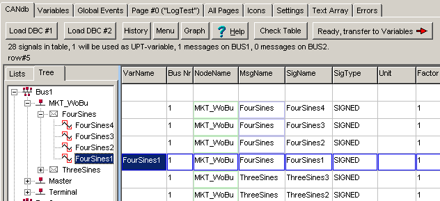
In this example, a CAN signal (here: "FourSines1") has been selected, and already connected to a variable (here: with the same name as the CAN signal).
You can either type a variable name in the left column of the table, of double-click into a line of the table to generate a variable name automatically from the CANdb signal name.
A double click into the VarName column of the definition table opens a popup menu where you can automatically generates a variable name, or remove it from the definition table. All signals which have a non-empty VarName in this table will later be copied into variable definitions (see next step).
Only select the CANdb signals which you really need in the application, because the total number of variables in a display application is limited ! The maximum count of variables depends on the firmware, typically up to 40 variables can be used in a small system, but significantly more in a system with plenty of RAM. You can find the exact value in the programming tool's General Settings tab sheet after uploading or downloading a program to or from the target (display).
After selecting some signals to be used as display variables as explained above, a status text on the CANdb import screen like this appears:
"5 signals in table, 4 will be used as variable"
To update this message and to check if the names are valid, click the button Check Table above the definition table.
- Caution :
-
- The CANdb signal import function is no replacement for a CANdb editor, it does not validate the table entries. You can, however, modify a few cells in the table if you find the contents are not correct (for example, if a CAN message identifier has been changed and you don't want to re-import the CANdb file).
- There is no possibility to write the changes you made in the table back into the CANdb file, so editing something in the table (except for the VarName column) is pretty useless. You should better edit the source (which is the CANdb file) and import the modified CANdb file again.
-
The contents of the table will be saved in the display program file ("application", *.cvt).
So you don't need the CANdb file in a later session.
The CAN signal definitions contained in the *.cvt-file may be used to decode a received CAN stream also in the 'CAN Snooper' (optional feature).
CAN messages which will be transmitted (from the device's point of view, along with the signals contained in the message) are marked in red colour in the tree view, while 'normal' signals (which are received from the device's point of view) are marked with green icons. Signals which have not been connected to a display-variable yet (and thus are neither transmitted nor received by the device) are shown with gray icons, as in the example below.
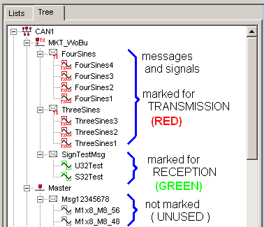
(Example with transmitted and received CAN signals;
taken from <programming tool>/programs/CdbSendT.cvt )
After selecting all signals which you need in your application (and supplying
proper names), you are ready for the next step - which is to generate a new
display variable for every selected CANdb-signal.
Transfer signal definitions to variables
<< previous step next step >>After at least one signal is selected to be connected to a display variable, the "Transfer" button will be enabled as shown here:
Click the button Ready, transfer to Variables button if all CANdb signals which you need in your application are selected (by supplying a variable name as described in the previous step).
The programming tool will then switch to the Variables page.
All variables which are connected to a CANdb signal will have a channel number of 30 in the variable definition table as shown:
Forget the column title "PDO/SDO-Definition" if a variable is connected to a CANdb-signal. In this case, it shows a part of the signal definition, including BUS-number, CAN-ID, Position of the least significant bit within the CAN telegram, count of databits for the signal, and a flag if the signal is in Intel- or Motorola format. Don't try to change the definitions here - it does not make sense to change anything in the signal definition here. Use a CANdb editor to modify the CANdb 'source file', then import the signal definitions from the CANdb file again !
For more information about the variable definition page, consult the manual of the programming tool (which is not "CANdb - specific"). The variable properties Min Value and Max Value are preset with the values from the signal definition in the CANdb file, but you can modify the properties if you need.
Usually, the programming tool automatically selects the best suited data type for the variable (integer, float, etc) when connecting it to a CAN signal. If that's not you want, the automatism can be turned off as explained here .
Unfortunately there is no default value for a signal defined in a CANdb file, so it's impossible to define a default value which shall be displayed on the CANview screen as long as no value has been received via CAN bus. Because the CANview terminal is only a listener(*), it cannot request the transmission of a signal (or message) from another devices - in contrast to the CANopen functionality mentioned in the programming tool's (main-) manual.
Special treatment of aperiodic signals
Another problem are signals with aperiodic transmission (or 'very seldom' transmission). If a signal is not used on the current page, it may not be received by the terminal, and if you switch to a page where is shall be displayed the value is not available. If this is a problem, set the variable's Update Time (alias Transmission Cycle) to APERIODIC. This forces the terminal to receive the message which contains the signal regardless if its used or not. See chapter "Strategy to allocate CAN message objects" in the appendix.
(*) The
original requisitions for the terminal were: "The terminal must receive only
but must not transmit"... then "It should receive only"... one
bad day "maybe it will have to transmit" ... in the meantime "oh, well, but
it must also transmit signals for our application" ..... oh dear ! ;-)
Develop and test the display application
<< previous stepAfter all required variables have been defined (with or without network connection), you can use them in the application as described in the programming tool's manual.
The easiest way to use a variable is to show its value on the LCD. For this purpose, create a new display page, add a few display lines, and select a variable for every display line where a numeric value shall be displayed. Use the asterisk (*) as a placeholder for the digits, a minus character (-) as placeholder for the sign and the dot (.) as a decimal point like in the following example:
The variable can be selected from a list on the right side of the display definition table.
For testing purposes, you can enter the name of a variable in the watch window of the programming tool. The current value of the variable will be shown there, assuming you have a suitable CAN bus interface connected to the PC.
The appearance of a programmed display page can be seen in the LCD simulator window, where you can also move most display elements with the mouse:
More information how to create, debug and modify an application can be found
in the (not CANdb-specific) programming tool
manual.
Specialities like icons, menus, event handling, etc are not explained here
in the CANdb-specific help file.
The next step would be transferring (e.g. uploading) the new application into a 'real' target device.
CAN database import options and other features (CAN related)
The previous chapter showed the basic procedure to create a new application with CAN signal- and message definitions imported from CAN databases (*.dbc files or similar).This chapter describes more options related to CAN database, and related features that can help you to 'update' or adapt an already existing application for a different vehicle (with a 'new' database).
Assigning Variables / CANdb-Signals to the lines of a display page
To assign variables / signals on an already existing (or recycled) display
page, use a special dialog which is described in another document, see
"Selecting (or replacing) VARIABLES or SIGNALS for a display page"
in the programming tool's general manual.
CANdb file import history
The CANdb file import history is basically a list of the last 8 CANdb files which have been loaded into the terminal application. The history of a new application is empty. You can look into the CANdb file import history by clicking the "History" button on the CANdb import screen.
The CANdb file import history may look like this:
(screenshot CANdb file history)
You can select one entry in this list, then click Ok. A file selector opens where the file from the history is already selected. This allows you to easily re-load signal definitions from an updated CANdb file.
Notes:
- This is only possible if the "old" file path is still valid !
- The newest entry is on top of the list, the oldest at the bottom. When loading the 9-th file (etc), the oldest history entry will be lost.
- The list is not sorted by file-date ("DOS-file-timestamp"), but by the sequence of loading.
- CAN bus number '255' is used as a dummy for all databases imported with option "All/Any" (i.e. received from all buses as if they were connected in 'parallel', or (for TX-signals) simultaneously transmit on all buses).
- If you want to see more characters of the file path, maximize the history window with the mouse.
-
The entire database-import-history can be erased through the database popup menu
(can be opened via the 'Menu' button on top of the 'CANdb' tab).
Of course this doesn't delete the CAN databases, but the history
of importing these files into the display application.
CAN database file import options
For one of our customers, the NODE- and MESSAGE names had to be ignored when overwriting old signal definitions (because in an updated database, only the signal names were the same, but nodes and messages had been named for some reason). By default, an old entry in the table will only be replaced if there is a complete match for NODE+MESSAGE+SIGNAL name. Click on the Menu button, then select CANdb File Import Options to change this.
(screenshot CANdb import options)
Options for CANdb file import:
- Ignore NODE NAME
-
If this option is selected, the programming tool does not care for a signal's
NODE name when it decides wheter an old entry in the signal table must be
replaced (overwritten) or if the signal read from a CANdb file shall be appended
(added) to the table.
(Regardless of this flag, the NODE NAME from the file will always be copied into the table; the "Ignore" action only applies to the comparation).
- Ignore MESSAGE NAME
- If this option is selected, the programming tool does not care for a signal's MESSAGE name when it decides wheter an old entry in the signal table must be replaced (overwritten) or if the signal read from a CANdb file shall be appended (added) to the table.
Note: Usually, either both of these options are OFF. You should only turn these options ON if you are absolutely sure that all SIGNAL NAMES in your applications are unique !
See also: Importing CAN databases (*.dbc, etc)
Re-importing CAN database files keeping display variables 'connected' to CAN signals
As already mentioned in chapter 2, CAN database files can be re-imported (aka "refreshed" or "re-loaded" from the source) without losing the connection between CAN signals (from the old database) and display variables.For that purpose, do not 'erase the whole table' before re-importing the database. Instead, just leave the old contents in the 'CANdb' definition table, and load (import) an updated CAN database. The programming tool will look for matching node-, message-, and signal names, and replace those entries in the table, leaving the already present variable names in place.
When encountering the first already existing signal name (usually in combination with the node- and message name), the programming tool pops up with a message asking you how to proceed:
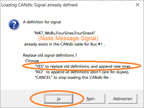
Confirm this with 'Yes' ('Ja' on a PC with german windows) to replace old (already existing)
signal definitions with the same name, and only append new signal definitions
at the end of the table.
Because the display variable names remain unchanged, and connected to CAN signals
(unless the re-imported databases use different signal names; in that case you will have
to find the new names yourself, and re-connect those signals to the display variables one by one).
New appended entries (yellow as in the screenshot above)
are not connected to diplay variables yet. If such signals are important
for your application, you can quickly generate new display variables for them
as explained in chapter 1 (right-click into the cell
in column 'VarName'). The yellow background makes it easy to spot such new entries
near the end of the table.
But in certain cases (for example if a 32-bit value shall be displayed in
binary form) it's better to let the programming tool select the best suited
data type, which is not necessarily floating point now. Since 2009-05, the
programming tool can determine the data type automatically, as follows:
If this automatism leads to compatibility issues with older display applications,
you can turn it off on the "CANdb" tabsheet:
Click the button Menü there, select Options for
converting CAN signals into Variables, and modify the option labelled
Datentyp der Variablen automatisch ermitteln ein- oder ausschalten.
Note:
If all signals are transmitted periodically, you can define a global
monitoring interval with this function:
If <interval> is not zero, signal monitoring is enabled. This means,
if any signal has not been received within the specified interval, it becomes
"invalid" (which is the default state after power-on). The unit of
<interval> is 0.1 seconds, so @signals.timeout=5 sets the interval
to 500 milliseconds.
If <interval> is zero, signal monitoring is disabled. This means, even
if a signal has not been received for a very long time, it remains "valid".
Function
of the signal timeout monitor
Notes
Only available for devices with CANdb-support, and ARM-CPU,
and firmware compiled 2009-08-21 or later !
For the class of devices mentioned above, it is possible to modify the definition
of interpreter variables during runtime, using the 'components' of a variable
which are listed here (external
document). This also applies to variables which are connected to CANdb-signals.
The following components can be used for that purpose:
The components listed above are also accessable
from the Script Langage.
After the last imported database, click on the (now flashing) button labelled
'Ready, transfer to Variables' to convert the updated data into display
variables (keeping the old names) as already explained in chapter 2.
Coloured cells in the CAN database display after (re-) importing files
Since 2021-01-15, the programming tool can assist you when importing or 'refreshing'
CAN databases from files by highlighting certain table rows as specified below.
All rows in the 'CANdb' table that have successfully been updated during the
last file import (instead of being freshly appended) will be highlighted
by a green-coloured background.
New table entries that have been appended to the table will be highlighted
by a yellow background.
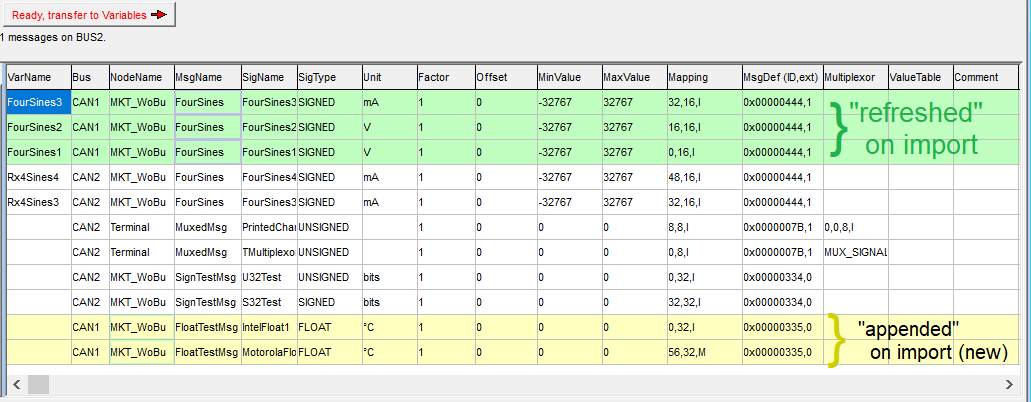
Coloured cells in the tool's 'CANdb' table after importing (refreshing) a database.
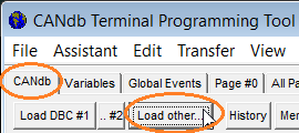
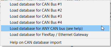
Popup menu to import databases for other buses / any bus
The 'Load other...'-button on the 'CANdb' tab (CAN database import)
opens the popup menu shown below. This menu can be used to import databases
for 'other' CAN ports (besides CAN #1 and CAN #2), and -if supported by the
device firmware- to import signals that shall be received from, or sent to,
any / all CAN buses. This may sound trivial but it's not,
because sending e.g. a CAN message identifier imported from a database to
all available CAN interfaces can cause an high bus load,
or even CAN message identifier collisions.
 →
→ 
Popup menu for other database-related operations
The 'Menu'-button on the 'CANdb' tab (CAN database import) opens the popup menu shown below:
Options for converting CAN Signal Definitions into Variables
In older program versions, CAN-signals were always converted into variables
with data type "floating point".
For integer values, things are different: Leading zeroes are usually not
suppressed, and the decimal point may be inserted "anywhere" for the display
(since integer values have no real decimal point). For example, a numeric
value of 255 may be displayed as "2.55" if you want it to. This not a bug,
it's a feature ! The reason is that older devices (with 8-bit CPU) didn't
support floating point numbers at all, and this was the only way to display
certain variables in their physical unit; and new devices (with 32-bit CPU)
shall remain functionally compatible with oder devices.
Signal Timeout Monitoring
A problem with the (original) CANdb file format was, that the transmission
cycle of signals and messages was nowhere specified, so there
was no "easy" way to detect a broken link between sender and receiver
(here: terminal). Since November 2003, the firmware has a simple signal timeout
monitor which works as described later.
@signals.timeout=<interval time in 0.1 seconds>
@signals.timeout=0
@sigs.tmo=0 (the same as above, abbreviated)
CAN.rx_timeout := <intervall in milliseconds>
@signals.timeout=0)
does not make all signals valid again ! A signal will become valid after
successfull reception.
@signals.timeout=5) many signals may become invalid immediately.
You should use this command only once in your program; perferably in the
"page enter"-event of your startup page
(page 0). Then it will be called once after power-on.
Special components of display variables for CAN signals
For example, assume a variable named "FourSines1" is connected to a CAN-message.
The numeric expression
FourSines1.ci
will return the CAN-Identifier of that message (including the 11/29-bit ID
flag in bit 29, and the bus number in bits 31..30).
The interpreter command
FourSines1.ci = 0x123
will set the CAN identifier to 0x123 (11-bit CAN-ID, because no extended-flag
is specified), and use the first CAN-bus (because no bus-number-flag is
set).
Note: the example above is taken from the demo application "MV2_DEMO.CVT",
page titled "Standard Signal Test", contained in the installation archive.
Also note that changing a signal's CAN-identifier may cause reprogramming
of the CAN-Controller, which in turn can cause temporary loss of received
CAN message (also for the internal CAN-logger) !
Returns a variable's optional 'value table', all in a single string, in the format specified here.
back to the chapter overview
Signal Value Tables
Certain signals may be displayed as text strings instead of numeric values.
For these signals, the CAN database (*.dbc file) may contain a string of signal value/text pairs, which can be imported into the programming tool. For example, a signal from a gearbox may contain the following value/text pairs:
255=SNA,0=P,1=N,2=R,3=D1,4=D2,5=D3,6=D4,7=D5,8=D6
If such value/text tables are imported from the CAN database (and transferred
into the appropriate variable definition), the terminal may show "P" (Park)
instead of "0", or "N" (Neutral) instead of "1", etc.
"SNA" often means 'Signal Not Available', and (for unsigned integers on CAN)
is encoded with all bits in the signal set.
NOTE: The numeric values appearing in these tables always seem to be RAW (non-scaled) signal values in the CAN database.
It seems to have been the intention of the original CAN database file format to allow a mixed display, depending on the signal value.
The display will proceed as follows if a signal is received from the CAN bus (for display elements configured as described here) :
- Unmap the RAW signal value from the received CAN message
- Check if there is a signal value table for this signal
- If there is, look for the RAW signal value in that table
- If there's a match, show the TEXT from that table.
Otherwise, proceed as if there was no value table: - Convert the RAW signal value into a PHYSICAL value (using the scaling factor and -offset)
- Show the PHYSICAL value on the screen (because there is no text string for the RAW value)
NOTE: The total length of such a table (as a single string, like the one
shown in the gearbox example above) may be restricted in size. We expect
127 characters per signal, requiring an additional memory 150 signals * 128
bytes/signal = approx. 20 kBytes . Only new devices (with 32-bit CPU and
sufficient RAM and ROM) will be able to support signal value tables at all.
For special applications, the script can retrieve the entire value table
(display.GetVarDefinition(<Variable-Name>).ValueTable).
Details about the 'CAN Message Layout' display window
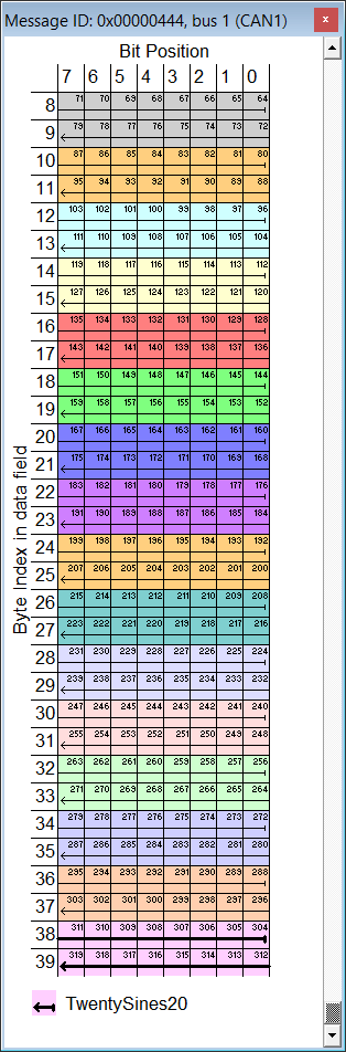
As already mentioned under importing signal definitions from DBC files, the programming tool contains a graphic 'CAN Message Layout' display window. Since 2020, that window does not only support CAN (with 8 data bytes per frame) but also CAN FD (with up to 64 data bytes in the message payload).
The screenshot on the left shows a part of the CAN FD data field, containing 20 signals with 16 bits each (as usual, click into the image to magnify it). Despite being magnified by the operator, the window may be too small to show the entire message (data field), so the programming tool automatically turns on a vertical scrollbar to control the byte offset within the message (see labels on the graphic's left edge - it shows those zero-based byte indices).
Of course the table's headline, and the legend in the lower part are not scrolled along with the table data.
A mouse click into the graphic message layout switches the currently selected signal. When selecting a different signal this way, the programming tool also switches the currently selected signal in the 'CAN' definition table.
If the clicked bit is used by multiple ("multiplexed") signals, you can switch through all signals by multiply clicking on the same bit in the table.
- Hint:
- Multiply clicking on a bit to show all signals sharing that bit also works with the CAN message layout display in the programming tool's CAN-Simulator.
The currently selected signal is marked by a thicker arrow in the graphic. The arrow starts at the signal's least significant bit, and ends with the arrow head at the most significant bit.
A similar display is used in Kvaser's free CAN database editor.
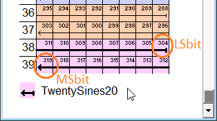
Magnified display of the currently selected signal
in the CAN / CAN FD 'Message Layout' window,
with signal name shown in the legend (bottom part),
and zero-based byte indices shown on the left side.
The numbering of bits within the entire data field uses the same (zero-based) principle as in the script language, regardless if the data field contains signals in "Motorola-Format" or not. Thus the 16-bit sample signal 'TwentySines20', spanning from bits 304 to 319(!), occupies the last 2 bytes of a hypothetical 40-byte frame.
Transmitting (sending) CAN signals with the display terminal
Certain terminals may also send CAN messages with up to 8 signals (per message), defined in a CAN database (*.dbc).
This rarely used, and potentially dangerous
function had to be implemented in autumn 2009 (thus it requires
a firmware compiled 2009-10-30 or later).
By default, the terminal only receives messages (from its own point
of view) but will never send anything unless you want it to.
-
Notes (because new users often had problems to put the transmission of
CANdb-signals to work):
-
-
The transmission of CAN-"signals" is is one of the
unlockable features
- ask the manufacturer if you need it !
If the device shows "CdbTX=NO" when invoking the system menu, the transmission of CAN-signals is impossible.
-
The flag 'signals.tx_exable'
or (in the script) CAN.tx_enable must be set
to enable transmission of CAN-signals this way
As long as this "tx_enable" flag has not been set, the transmission of CAN-signals is impossible.
-
If the CAN CONTROLLER isn't allowed to send (via system setup),
the transmission of CAN-signals is impossible.
-
This hasn't got anything to do with the interpreter's
ctx command (CAN transmit),
which existed since MKT's very first "CANdb" display terminal was built in 2002.
-
Don't stop reading at this point. Please read the entire chapter.
If you cannot invest those 5 minutes to read this chapter, you will get in trouble later anyway..
-
The transmission of CAN-"signals" is is one of the
unlockable features
Warning:
-
You should be very familiar with your CAN network, and know
exactly what you are doing, before you even think about sending CAN
messages from your application, because this can cause severe trouble, serious
accidents, damage to persons, or even worse, if improperly used !
(Think about this: By accident, your terminal application sends 'the wrong' message to an airbag unit, while driving at 120 miles per hour.
Or, sending the same CAN idenfier from two different devices may cause severe network errors ).
You have been advised ! The entire risk of using this feature is yours !
The easiest way to inform the terminal which messages shall be sent (transmitted
from the terminal's point of view) is to set the terminal's own node name to one
of the node names in your CAN database. ( Hopefully you used 'speaking' names
for all those CAN nodes, right ? )
If you did, and you are really sure about what you're doing, switch
to the programming tool's CAN tab, and click on
Menu.
In the popup menu, select Node Name for CAN Transmission. Then
enter the name of the node (from the database) which contains the definitions
of all messages and signals which your terminal application
is going to send.
All CAN messages of that node, and all signals of those messages, will then
be marked for TRANSMISSION in the CANdb table. When converting these signals
into variables, they will be marked as 'TX' (in the Access column
of the variable definition table).
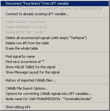
To mark a single signal (and, along with that, a CAN message) for transmission, select the menu item
- Connect "XYZ" (signal name) to a new variable for Transmission
from the context menu on the CAN tab.
- Background info:
-
Selecting a signal for transmission will add a transmit flag (
"T") in the signal definition table, in column titled "Mapping".
Later, when parts of the CANdb table are converted into variables, all variables selected for transmission will have the Access attribute set to TX, which means 'Transmit' from the terminal's point of view.
(Example with transmitted and received CAN signals;
taken from <programming tool>/programs/CdbSendT.cvt )
Unfortunately a 'normal' CAN database (*.dbc) doesn't contain any info
if and when a CAN message shall be transmitted.
As a clumsy solution, we use the following principle for sending:
-
If any signal mapped into the CAN-message has a non-zero "Update Time" (here:
transmission cycle; specified in milliseconds on the
Variables tab),
the message will be sent periodically at the lowest "Update Time" found in any of the signals contained in the message; -
If none of the mapped signals has a non-zero "Update Time", the message will
not be sent periodically (because we don't know the
TX-interval).
Instead, the message will only be sent if its contents (8-byte data field) has been modified by the mapping process; -
As long as the global flag
signals.tx_enableis zero, none of the 'CANdb-messages' will be sent
(neither periodically, nor event driven as explained above). The ctx command, however, is not affected by this flag. Example:
@signals.tx_enable = 1 : REM enable transmission of CAN
    signals
The minimum transmit cycle (time in milliseconds) could not be specified
at the time of this writing (2009-11-24), but you may expect that 10 millisecond
intervals (or 100 messages per second) will be possible, as long as the CAN
bus timing permits.
An example to send 'CANdb' signals
A sample application using transmit signals is in the file programs/CdbSendT.CVT . In that example, four variables ("FourSines1" to "FourSines4") are connected to CAN signals, which can be periodically transmitted. To start transmitting, press the softbutton 'Transmission: DISABLED' so that the button changes to 'Transmission: ENABLED'.Three other variables ("ThreeSines1" to "ThreeSines3"), connected to signals in a different CAN message, and using a different transmit cycle ("Update Time" on the variable definition tab).
![]()
(Screenshot from 'CdbSendT.cvt' - CANdb Send Test application)
On the second page of that test application, a few received values are displayed ("Rx4Sines1" to "Rx4Sines4"). For this test, you will need a device with TWO CAN-buses (CAN1 to transmit, CAN2 to receive). Connect both buses, enable the transmission, and watch the received values (they are shown numerically or as an Y(t) diagram). Because all of these signals are sine waves with different frequencies (generated in a few event definitions), they are easy to discern.
If you have no real hardware, you can test the CAN signal transmission with the simulator (watch the transmitted CAN signals on the 'Error / Messages' tab), but the CAN transmission in the simulator suffers from severe timing jitter, and the transmit intervals are limited to about 100 milliseconds (or more). The 'real' hardware doesn't suffer from this, because it uses a dedicated timer hardware, and a preemptive multitasking system with very low task switch latencies, which cannot be emulated on a windows PC.
See also (related with the transmission of CAN / CAN FD frames):
- Sending CAN / CAN FD messages from the programming tool's CAN Simulator
- Sending CAN / CAN FD messages from the programming tool's logfile replay utility
- Sending CAN / CAN FD messages from the programmed device, using scripts
Appendix
The appendix contains some additional info, which you don't need for 'normal' operation. You don't necessarily have to read and understand this ...but please take a look at the legal terms !
Strategy to allocate CAN message objects (for old devices with 'FULL-CAN' controller)
Only applies to outdated devices like 'MKT-View Plus' !
The CAN controller inside the terminal is a so-called FULL CAN controller. There are up to 13 hardware receive buffers in it ('message objects'). Each of these receivers is configured to receive (or sometimes to transmit) one particular CAN-identifier. So for a single bus, a maximum of 13 different messages (with different CAN-identifiers) can be received by the terminal.
The terminal's problem is, there may be more different CANdb signals/messages in your application than can be received with the CAN-controller. The terminal's firmware uses the following strategy to solve this problem:
-
Whenever a display page switch occurrs, all "currently used" variables are
detected and CAN receivers are allocated to receive these variables
("signals").
If not enough receivers are available, all receivers which have been allocated previously are de-allocated (with signals from 'old' display pages) and step 1 is repeated. - If -after step 1- more unused receivers are avaliable, more receivers are allocated for messages (with "CANdb-signals") which are sent APERIODICALLY.
- If -after step 2- even more unused receivers are available, the remaining receivers are allocated for other "currently unused" variables with any transmission cycle.
Result: Chances are good that the value of a variable is immediately avaliable after switching to another display page.
If your application uses less than 13 different CAN messages (on one bus),
all variables are received at any time and you don't have to care about
this.
(Remember: A CANdb-message usually contains more than one CANdb-signal, so
chances are good you have less than 13 messages. The "CANdb" tab of the
programming tool shows you how many different messages are received for every
bus).
Unfortunately the imported CANdb files don't deliver the info if a message is transmitted periodically (or even "frequently") or aperiodically (or "very seldom"). For this reason, YOU can give a variable(!) the attibute "APERIODIC transmission" on the "Variables" tab of the terminal programming tool. Enter an "A" in the column "UPDATE TIME" (which, for CANdb-signals, may be called "Transmission Cycle"). After clicking Apply this will be displayed as "APERIODIC".
By the way, the terminal was never intended to SEND CANdb-messages itself. If one day it shall be able to send (on request via RTR, which is common practise), there will be less than 13 different RX-messages, so a clever strategy to allocate the few receivers will be even more important.
- Background info:
- It is impossible to receive "everything" in an interrupt-driven buffer when you don't know the amount of BUS traffic, especially not in the case of this programmable terminal. There may be many thousand CAN messages per second rushing in, too much for this CPU. The only exception to this rule are display terminals with integrated CAN-logger, where a large buffer in RAM is used to handle all CAN messages received by the display (application) and the CAN logger.
Legal Terms, Disclaimer
Namings for products in this manual, that are registered trademarks, are not separately marked. The same applies to copyrighted material. Therefore the missing ®(r) or ©(c) does not implicate, that the naming is a free trade name. Furthermore the used names do not indicate patent rights or anything similar.
CANdb® is registered trademark of Vector Informatik GmbH
NTCAN API© is copyright by ESD electronic system design GmbH
PCAN Dongle and the PCAN API© is copyright by PEAK-Service GmbH
Microsoft, Windows, Win95, WinNT, WinXP® are registered trademarks of Microsoft Corporation
The 'SmallPort' utility was written by Alexander Weitzman
The software and accompanying written materials (including instructions for use) are provided "as is" without warranty of any kind. Further, MKT Systemtechnik does not warrant, guarantee, or make any representations regarding the use, or the results of the use, of the software or written materials in terms of correctness, accuracy, reliability, currentness, or otherwise.
The entire risk as to the results and performance of the software is assumed by Licensee and not by MKT Systemtechnik or its distributors, agents or employees.
THERE ARE NO OTHER WARRANTIES, EITHER EXPRESS
OR IMPLIED, INCLUDING BUT NOT LIMITED TO
IMPLIED WARRANTIES OF MERCHANTABILITY AND FITNESS
FOR A PARTICULAR PURPOSE,
WITH RESPECT TO THE SOFTWARE, THE ACCOMPANYING
WRITTEN MATERIALS, AND ANY ACCOMPANYING HARDWARE.
MKT Systemtechnik
Haßkampstraße 75-77
32257 Bünde (Germany)
Phone: 05223/493933-0
Fax: 05223/493933-20
Last modifications (document revision history)
- 2024-10: Additions for devices with "CAN FD" (supporting up to 64 bytes in the data field), e.g. MKT-View V
- 2021-01: Rearranged document structure, added notes about 're-loading' CAN database files.
Still in a 'very early state of experimentation': Import of *.arxml (besides *.dbc). - 2020-02: CAN FD support, with up to 64 bytes per data field.
- 2015-06: Added links and anchors for the script language / CAN.DecodeMessage(), etc.
- 2011-06: Added the notes about CAN-via-UDP
- 2009-10: First attempts to send CAN-messages with signals definitions from CANdb files (*.dbc)
- 2003-12: Treatment of received CAN messages completely rewritten, because
multiplexed signals were sent in bursts somewhere.
Now using an interrupt-driven buffer for all received messages. - 2003-11: Signal timeout monitor implemented
- 2002-10: added CANdb file import history and description of FULL-CAN-message allocation strategy
- 2002-09: added notes about duplicated signal definitions